![]()
![]()
|
|
|
![]() Task area Shadow
Task area Shadow
You can use this tool to insert 3D models in bitmap images, for example, a planned building in a photograph of the planned site. In addition, you can identify the eye point, target point and the vanishing points in a scanned photograph.
Optical distortion of photographic lenses and the section scanned of the photograph combined with the resolution of the screen restrict the accuracy of this operation. This means that corrections or even a number of attempts may be necessary until you are satisfied with the result.
Before you insert a complex architectural structure, use a simple outline model of the same shape, consisting of 3D objects. Once it fits, you can save it before you replace it with the complex model.
Note: This tool is particularly useful for perspective views in which vanishing points are clearly visible. For example, think of corner buildings. Aerial views, however, are not so suitable.
To mount a 3D model in an image
Tip: In the 3D View palette, set the Focal length so that it matches the value used for the photo. For digital photos, you can find this value in the Properties of the file - Details - Focal length of 35mm.
Tip: You can also set the perspective view in a viewport with the Animation view type.
All you need to do is click ![]() Match parameters in the 3D View palette. Then click within the viewport with the Animation view type. This is only possible if
Match parameters in the 3D View palette. Then click within the viewport with the Animation view type. This is only possible if ![]() Navigation Mode is not active
Navigation Mode is not active
Tip: You can make things easier by creating a hidden line image of the model: Select the Hidden line image view type at the bottom of the viewport.
The program opens a window with the 3D model. The window's height:width ratio matches the photograph's height:width ratio.
If the bitmap image of the photograph is larger than the display resolution, it is fitted into the workspace.
Note: Enter the angle included by the two pairs of vanishing lines in plan view.
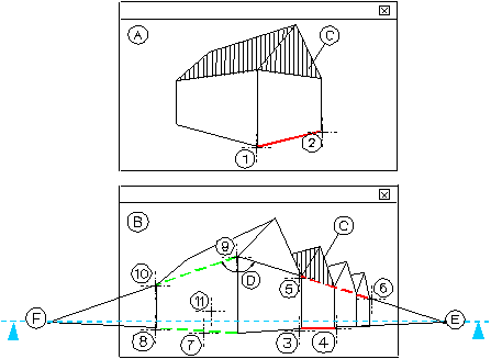
(A) 3D model
(B) Photo
(C) New building
(D) This angle must be known in plan view (see step 11).
(E) First vanishing point (not visible)
(F) Second vanishing point (not visible)
Note: The two vanishing points (E) and (F) must be at the same height.
(1)+(2) Identify the reference line on the 3D model. The photograph is hidden (see step 8).
(3)+(4) Click a corresponding reference line in the image. The photograph will reappear (see step 9).
(5)+(6) Specify a second line leading to the same vanishing point (see step 9).
(7)-(10) Specify two lines leading to the second vanishing point (see step 10).
(11) Place the target point. You can place it as often as necessary - until you have found the correct one and while the tool is still active (see steps 12/13).
Tip: Draw the required reference lines in a copy of the bitmap image and use this copy to fit in the model. To render the model subsequently, click ![]() Surroundings (How) and select the image without vanishing lines.
Surroundings (How) and select the image without vanishing lines.
The photograph will reappear after you have done this.
Note: When the message The horizon is inclined at 1.5 degrees. An inclined horizon cannot be displayed. appears, do the following:
The 3D model is redrawn on top of the photograph.
Now you can save the correct target point and use it for the calculation of the complex model.
Note: Using ![]() Surroundings (How), you can activate or deactivate a bitmap image for the background at any time.
Surroundings (How), you can activate or deactivate a bitmap image for the background at any time.
Note: The perspective view is displayed as a wireframe model. You can use the ![]() Render tool to render the perspective view with the photo (bitmap image) in the background.
Render tool to render the perspective view with the photo (bitmap image) in the background.
Note: You do not need a Virtual ground plane for rendering an image with a bitmap image in the background. Open the ![]() Surroundings tool (How) and switch the ground plane off.
Surroundings tool (How) and switch the ground plane off.
|
(C) ALLPLAN GmbH |
Privacy policy |