![]()
![]()
|
|
|
![]() Task area Meshes
Task area Meshes
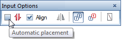
As an alternative to manual entry, you can also use the ![]() Mesh Shape tool to create reinforcement in expanding mode. Automatic placement is also possible.
Mesh Shape tool to create reinforcement in expanding mode. Automatic placement is also possible.
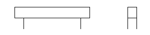
The following example shows how to enter a rectangular bent-up mesh as an expanding bending shape using the ![]() Mesh Shape tool. The Expand to adapt to edges option is selected in the input options. The reinforcement is then labeled and placed automatically.
Mesh Shape tool. The Expand to adapt to edges option is selected in the input options. The reinforcement is then labeled and placed automatically.
For example: entering and placing a bent-up mesh in expanding mode |
||
Requirement: |
|
|
1 |
Method 1: 3D model on |
Reinforce with 3D model option is active or not ( |
2 |
Click tool |
|
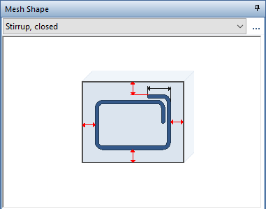
3 |
Select Stirrup, closed in the list box at the top in the Mesh Shape palette |
|
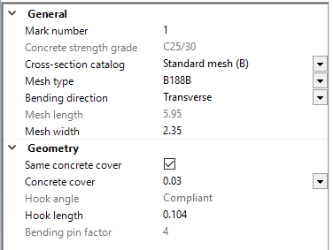
4 |
Set the mesh parameters and specify the position of the bending shape |
|
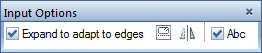
5 |
Select Expand to adapt to edges in the input options |
|
6 |
Move cursor over cross-section and confirm found position |
|
6a |
Methods 1 and 2 if you defined the mesh shape outside a view: |
|
7 |
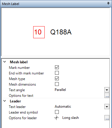
Press ESC when labeling was active when you entered the bending shape or select |
|
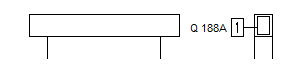
Result: |
|
|
After this, Allplan immediately switches to the ![]() Place Mesh Shape tool. Methods 1 and 2 (if you defined the mesh shape outside a view) and method 3 only allow manual placement. First define the placing region and then the view or start by defining the viewing direction followed by the placing region.
Place Mesh Shape tool. Methods 1 and 2 (if you defined the mesh shape outside a view) and method 3 only allow manual placement. First define the placing region and then the view or start by defining the viewing direction followed by the placing region.
With methods 1 and 2 (if there is a view that is orthogonal to the input view), you can decide whether to place the mark manually or automatically after entering it.
However, you can also cancel placement and select the ![]() Place Mesh Shape tool later. After this, however, automatic placement is no longer possible.
Place Mesh Shape tool later. After this, however, automatic placement is no longer possible.
7a |
Methods 1 and 2:
|
|
|
(C) ALLPLAN GmbH |
Privacy policy |