![]()
![]()
|
|
|
The new ![]() Axis Grid tool in the Grid task area (Design task) provides a completely new way of creating axis grids. You can use the new axis grid to design both in 2D and in 3D.
Axis Grid tool in the Grid task area (Design task) provides a completely new way of creating axis grids. You can use the new axis grid to design both in 2D and in 3D.
Axis grids from earlier versions were renamed 2D axis grids and can still be modified using the shortcut menu. You can find the ![]() 2D Axis Grid tool in the More tools with icons category on the Customize tab of the Customize dialog box.
2D Axis Grid tool in the More tools with icons category on the Customize tab of the Customize dialog box.
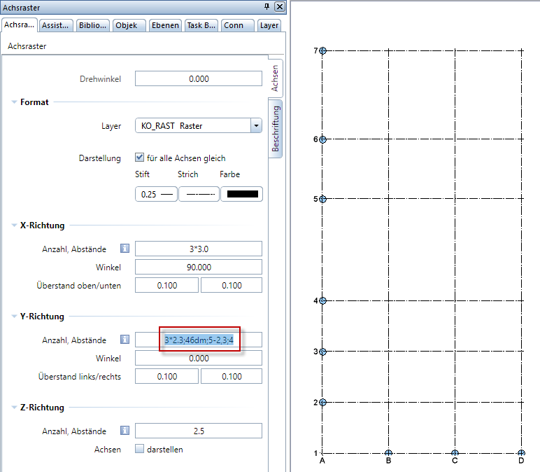
The two Axes and Label tabs of the new tool include all parameters of the old tool. In addition, you can define the layer of the axis grid, angles for the axes, a rotation angle for the axis grid and planes in the Z-direction.
By entering spacing values, you define how many axes you want to create in the X-direction and Y-direction or how many planes you want to create in the Z-direction. Use semicolons to separate the spacing values. Use commas or dots to separate the leading digits from the decimal places. You can only enter positive values. You can add the unit; this is optional. Basic arithmetic calculations are possible:
For example: Entering 3*2.3; 46dm; 5-3.2; 4 with a unit of length being set to [m] generates 7 axes spaced at 2.3m multiplied by 3, 4.6m, 1.8m and 4.0m.
Modifying axis grids
Compared with the old tool, the new axis grid can be modified more easily and intuitively. Simply click the axis grid with the left mouse button to select and modify the axis grid. Double-click an element of the axis grid with the left mouse button to open the ‘Properties’ palette. Now the axis grid is in modification mode. In modification mode, you can modify the parameters of the axis grid in one of the following ways:
Note: After you have placed the axis grid in the workspace, the axis grid is still in modification mode and can be adjusted.
|
(C) ALLPLAN GmbH |
Privacy policy |