![]()
![]()
|
|
|
Using the new ![]() Sweep Bars Along Path tool in the Bar Reinforcement module, you can easily reinforce doubly curved structures with varying cross-sections - such as bridges - in no time at all. The resulting reinforcement is both BIM-compliant and a 3D model. This tool places reinforcing bars, which you defined in one or more cross sections, along any sweep path. Using various paths, this sweep path describes the transitions between the cross-sections. You can formulate various rules defining how to create benching or splices, for example.
Sweep Bars Along Path tool in the Bar Reinforcement module, you can easily reinforce doubly curved structures with varying cross-sections - such as bridges - in no time at all. The resulting reinforcement is both BIM-compliant and a 3D model. This tool places reinforcing bars, which you defined in one or more cross sections, along any sweep path. Using various paths, this sweep path describes the transitions between the cross-sections. You can formulate various rules defining how to create benching or splices, for example.
In addition to ![]() Extrude Bars Along Path, this freeform reinforcement tool is the counterpart of the
Extrude Bars Along Path, this freeform reinforcement tool is the counterpart of the ![]() Sweep Path tool in the 3D Modeling module.
Sweep Path tool in the 3D Modeling module.
Requirements for placing reinforcing bars
The following requirements must be met so that the program can place the reinforcing bars:
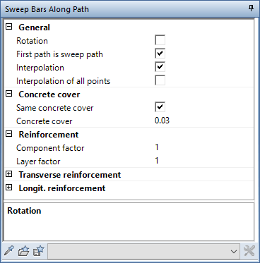
General parameters
You can place transverse reinforcement and longitudinal reinforcement, which you defined in one or more cross-sections, along any sweep path. This sweep path consists of at least one path. It may be useful to place the transverse reinforcement and the longitudinal reinforcement separately. In this case, it is sufficient to define the longitudinal reinforcement only in one cross-section. If the cross-sections include transverse reinforcement with an identical mark number, the segment lengths of the bar shape remain unchanged. Otherwise, the program creates a polygonal placement.
Use the Rotation option to place the transverse reinforcement so that it is always perpendicular to the first path of the sweep path. Otherwise, the program interpolates the position of transverse reinforcement between neighboring sections.
Use the First path is sweep path option to define the path clicked first as being part of the sweep path. In this case, the program will take this path into account when interpolating the bending shape points. Note that the first path is the path along which the program will apply the placement parameters.
Use the Interpolation option to control how far transverse reinforcement will be placed from the component edges. If this option is not selected and there are several paths, only the main path will be used for all bending shape points.
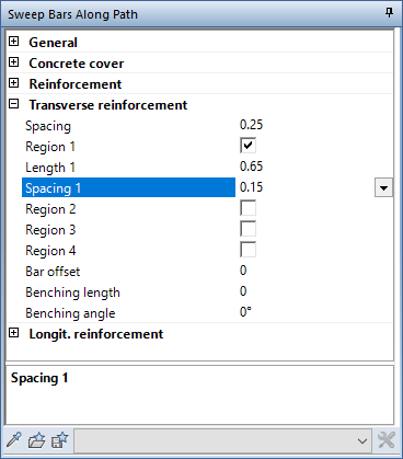
Parameters for transverse reinforcement
Define the spacing for Transverse reinforcement. Allplan will apply this spacing along the first path. By defining a value for the Bar offset, you create an offset between the bending shapes of transverse reinforcement.
You can create two regions with different spacing at the start and end of the placement. Define the length and spacing for each region. Allplan places the first or last bending shape of transverse reinforcement with the defined concrete cover in the first or last region respectively. The first bending shape of the other region follows at the offset specified for this region. Allplan places transverse reinforcement in the remaining region so that the reinforcement is centered.
To avoid excessive spacing in the areas where the regions meet, Allplan creates an additional bending shape of transverse reinforcement. This bending shape is outside the length you defined for the region.
In addition, you can enter a Benching length and a Benching angle for transverse reinforcement. This way, you can reduce the number of different marks.
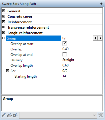
Parameters for longitudinal reinforcement
Longitudinal reinforcement combines all bars with the same mark number to form one group. ![]() and
and ![]() take you from group to group. You can define the following settings for each group:
take you from group to group. You can define the following settings for each group:
|
(C) ALLPLAN GmbH |
Privacy policy |