Drawing B-splines
Using the  3D Spline tool, you can draw two types of B-splines:
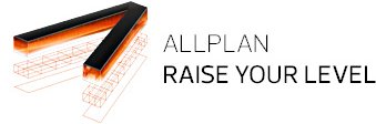
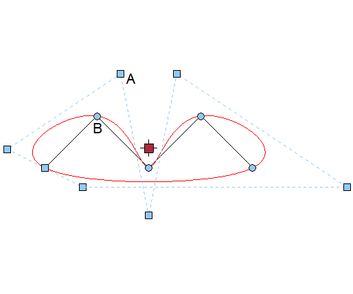
 B-spline from control points (open or closed)
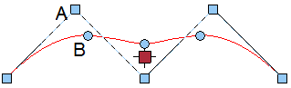
A Control point (2 of 5)
B Interpolated point on B-spline (2 of 5)
Distance between the control points: x=1, y=1 or -1
 B-spline from interpolated points (open or closed)
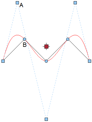
A Control point (2 of 5)
B Interpolated point on B-spline (2 of 5)
Distance between the interpolated points: x=1, y=1 or -1
More input options
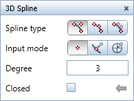
- Input mode
 Custom
Click to enter any control points of the 3D spline. You can even click points on existing elements. Match points from element
You can enter the control points of the 3D spline freely. If you click an existing element (for example, a 3D polyline), the program uses all points of this element as control points. Match terrain points
You can use terrain points as control points of the 3D spline. You can select these terrain points by clicking them or by enclosing them in a selection rectangle. For example, this option is useful for road location lines.
Using this option, you can create road location lines much faster than in previous versions. Instead of using the road location line as a 3D polygon, you can now use B-splines without losing precision.
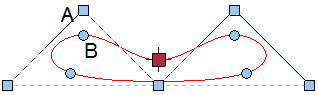
- Degree (B-splines only):
Define the degree for calculating the segments of the 3D spline (1 to 10). The greater the degree, the smoother the spline. Degree 3 is set by default; Degree 3 or Degree 4 is usually sufficient. You need to increase this value when you import data from Rhino, for example. Degree 1 produces a polygon. The number of control points defines the maximum value for Degree. - Closed:
The program automatically connects the last point and first point you entered, thus producing a closed 3D spline.
Note: To create B-splines, you can only use the 3D Spline tool in the Modeling task area (or in the 3D Modeling module). The  Spline tool in the 2D Objects task area (or in the Draft module) creates cubic splines.