![]()
![]()
|
|
|
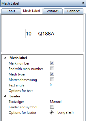
![]() Module(s): Mesh Reinforcement
Module(s): Mesh Reinforcement
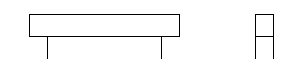
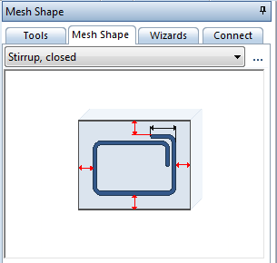
The following example shows how to use the ![]() Mesh Shape tool to enter a rectangular bent-up mesh by specifying points. The Expand to adapt to edges option is not selected in the input options. If there is an associative view or associative section of the 3D components, automatic depth placement is possible.
Mesh Shape tool to enter a rectangular bent-up mesh by specifying points. The Expand to adapt to edges option is not selected in the input options. If there is an associative view or associative section of the 3D components, automatic depth placement is possible.
The other bending shapes are entered in the same way. For more information please consult the help for Allplan.
For example: entering a bent-up mesh by clicking points on an outline |
||
Requirement: |
|
|
1 |
Method 1: 3D model on |
Reinforce with 3D model option is on or off ( |
2 |
Click tool |
|
3 |
Select Stirrup, closed in the list box at the top in the Mesh Shape palette |
|
4 |
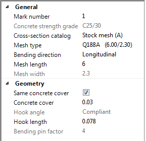
Set the mesh parameters and specify the position of the bending shape |
|
5 |
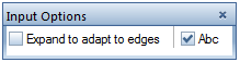
Deactivate Expand to adapt to edges in the input options |
|
6 |
Click points in the cross-section 1st and 2nd point --> ESC --> 3rd point |
|
6a |
With methods 1 and 2 if you defined the mesh shape outside a view: |
|
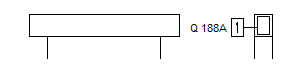
7 |
Press ESC when labeling was active when you entered the bending shape or select |
|
Result: |
|
|
After this, Allplan immediately switches to the ![]() Place Mesh Shape tool. However, you can also cancel and activate this tool later.
Place Mesh Shape tool. However, you can also cancel and activate this tool later.
A bent-up mesh is placed in the same manner as a stirrup.
|
(C) ALLPLAN GmbH |
Privacy policy |
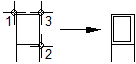 3rd point = position of overlap