![]()
![]()
|
|
|
![]() Module(s): Associative Views + Bar Reinforcement + Mesh Reinforcement + BAMTEC
Module(s): Associative Views + Bar Reinforcement + Mesh Reinforcement + BAMTEC
Method 1: applying reinforcement based on a 3D general arrangement drawing
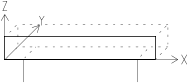
As the reinforcement is placed in a modeled shell in method 1, the program automatically detects its orientation in three-dimensional space.
Method 2: applying reinforcement based on a 2D general arrangement drawing
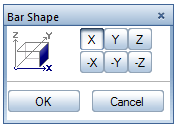
The two-dimensional shell in method 2 does not provide the information required for the orientation of the placed reinforcement in three-dimensional space. It is therefore necessary to indicate the position of the reinforcement to the program.
|
|
Elevation (Y) |
Section (X) |
|
|
|
|
Plan (-Z) |
|
||
|
Tip: Start your reinforcement drawing by placing stirrups in the X direction in the beam, placing stirrups in the -Z direction in the column or area reinforcement in the -Z direction in the slab. By clicking one of these views, you can define the orientation of all subsequent placements in three-dimensional space.
| (C) Allplan GmbH | Privacy policy |