![]()
![]()
|
|
|
The ![]() Unfold Shell tool has been moved from the
Unfold Shell tool has been moved from the ![]() Shell module to the
Shell module to the ![]() 3D Modeling module. In addition, this tool has been revised completely so that you can now use it to unfold any 3D solid. Using this tool, you can display an angled structure at its actual length.
3D Modeling module. In addition, this tool has been revised completely so that you can now use it to unfold any 3D solid. Using this tool, you can display an angled structure at its actual length.
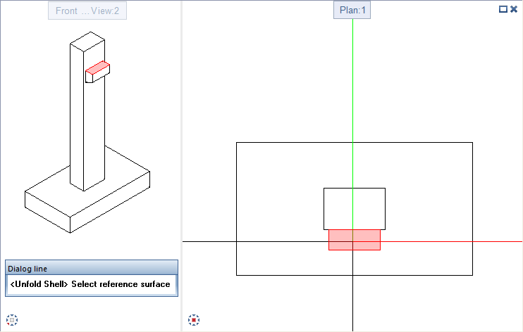
After you have selected and placed the reference surface, click the edge to which you want to attach the next surface to be unfolded. Do the same with the other edges until you have unfolded all surfaces.
When you are selecting the reference surface and the surfaces to be unfolded, these surfacers are highlighted in the 3D solid as transparent areas in the detection color set in the ![]() Options. So it is a good idea to work with multiple viewports.
Options. So it is a good idea to work with multiple viewports.
Each surface of the 3D solid can be unfolded only once. This prevents inapplicable and misleading representations.
When you point to an edge of which the adjoining surface can be unfolded, a preview of the surface is displayed. Otherwise, you can see a corresponding symbol in the workspace and the program displays a message to this effect in the dialog line.
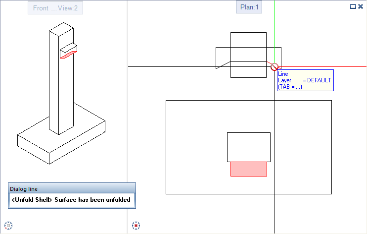
When you have unfolded all surfaces of the 3D solid, the program displays an appropriate message and automatically quits the tool.
Note: You can no longer unfold shell entities in the ![]() Shell module. Copy the shell entity to a new, empty drawing file and delete all views and sections using
Shell module. Copy the shell entity to a new, empty drawing file and delete all views and sections using ![]() Delete View/Section. As soon as you delete the last view, the shell entity is automatically converted to non-associative 3D elements, which can then be unfolded.
Delete View/Section. As soon as you delete the last view, the shell entity is automatically converted to non-associative 3D elements, which can then be unfolded.
The same applies to architectural elements; they cannot be unfolded using this tool. You first need to convert the architectural elements to 3D solids using the ![]() Convert Elements tool.
Convert Elements tool.
| (C) Allplan GmbH | Privacy policy |